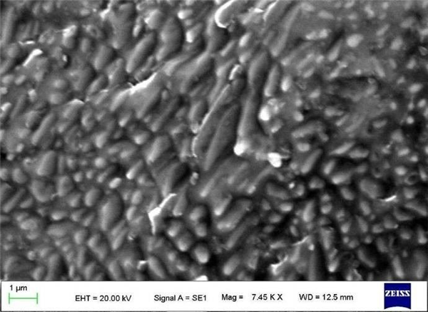
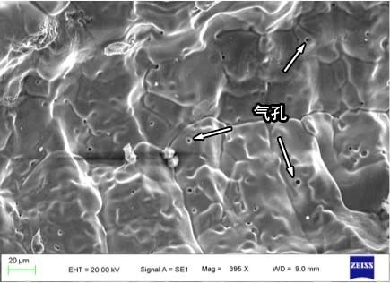
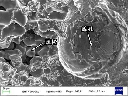
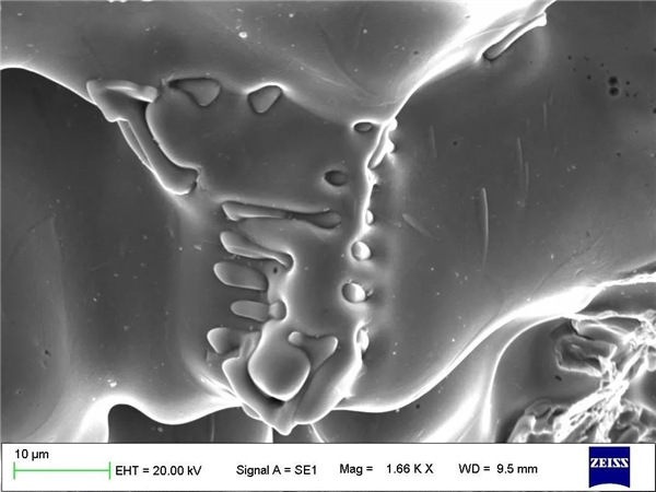
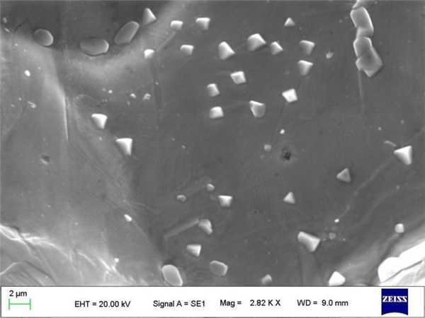
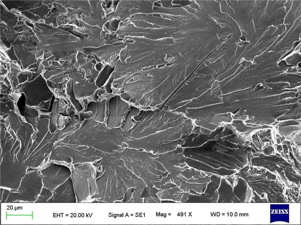
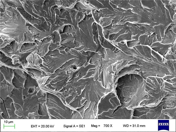
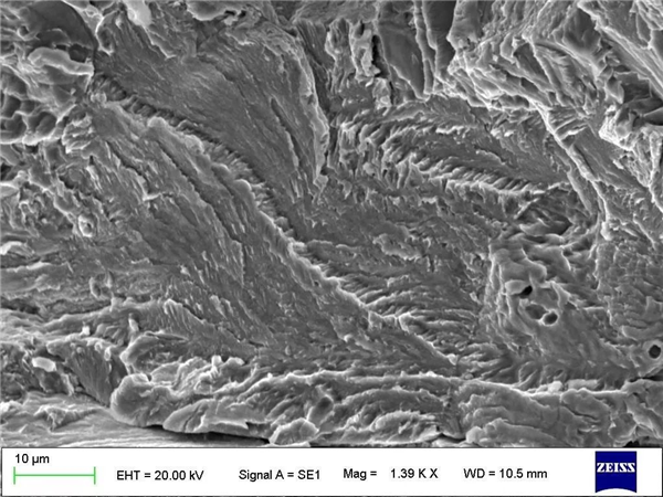
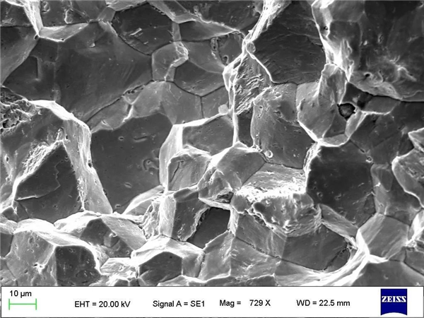
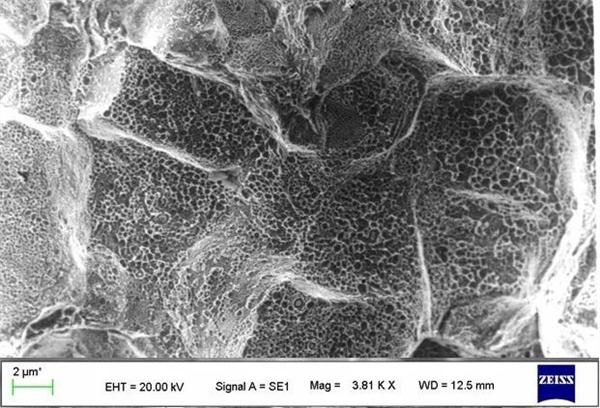
Foreword The development of fracture analysis of steel materials has been mainly carried out in three stages: the direct observation stage of the naked eye, magnifying glass and optical microscope; the indirect observation stage of the fracture replicating by transmission electron microscopy; and the direct observation stage by scanning electron microscopy. Because the fracture is a rugged rough surface, the microscope used to observe the fracture should have the maximum depth of field, the widest possible magnification range and high resolution, and the scanning electron microscope can meet the above comprehensive requirements, so the fracture analysis is now Scanning electron microscopes were used. Scanning electron microscopy (SEM), as the most widely used analytical instrument in modern materials science, has important applications in many fields. The applications in steel material analysis include: microstructure, microstructure and composition analysis of materials; material fracture analysis; material failure Analysis; material real-time micro-area composition analysis, elemental quantification, qualitative component analysis, rapid multi-element surface scanning and line scan analysis; material crystal, grain phase identification, grain size, shape analysis, crystal, grain orientation measurement, etc. . Some metallurgical defects will occur during the iron and steel smelting and casting process, causing cracking or fracture during subsequent processing or use of the product. Microscopic observation and analysis of the fracture of the product by scanning electron microscopy, finding the cause, and proposing improvement and preventive measures are of great significance. The following is a brief introduction of the microscopic morphology and formation causes of several typical billets and steel fractures. First, the continuous casting billet along the crystal cracking fracture In the fracture of the continuous casting billet, the crack is often observed along the coarse columnar grain boundary, and the grain boundary exhibits a free solidification high temperature cracking smooth feature (see Figure 1). The reason for this is mainly due to the high casting casting temperature, the unstable pulling speed or the fast pulling speed. Fig.1 The continuous casting billet is cracked along the coarse columnar grain boundary, and the microscopic characteristics of free solidification and smooth high temperature cracking appear on the grain boundary. Second, continuous casting billet coarse columnar crystal, pores, loose and shrinkage hole defect fracture When the gas content in the steel is high, there are many small pore defects along the crystal fracture in the middle of the cross section of the continuous casting billet (see Figure 2 above); when the continuous casting process is poorly controlled, the shrinkage is insufficient. More loose defects and larger size shrinkage defects can be observed on the fracture of the core portion of the cross section (see Fig. 2 below). Defects such as porosity, severe looseness, and shrinkage can adversely affect the quality of the finished product. Fig. 2 Microscopic characteristics of small porosity defects, core porosity and shrinkage defects on columnar grain boundaries in continuous casting billets 3. There are two forms of sulfide fractures on the grain boundary of the continuous casting billet. Non-metallic inclusions in steel cannot be completely eliminated. Scientifically and effectively controlling the type, size, distribution and shape of inclusions can reduce the damage to steel while reducing its content as much as possible. There are fewer types of sulfide inclusions, the most important being MnS. MnS cannot be formed in molten steel, and sulfide segregation is precipitated between dendrites due to segregation of sulfur during solidification of steel. The faster the cooling rate, the smaller the precipitated sulfide particles, but the number increases. With the difference of oxygen content in the steel, there are three types of sulfide inclusions in the continuous casting billet. The class I sulfides are irregularly distributed and larger spherical shapes, which are visible in boiling oxygen and semi-killed steel with high oxygen content. It is precipitated at the same time as the iron crystal at the beginning of solidification. Class II sulfides are network-like or dendritic crystal-like distributions that are formed during the late solidification. Class III sulfides are irregularly distributed small particles or small blocks which are clearly visible on the sides, corners and faces. They occur in excess aluminum deoxidized steel due to the spontaneous formation of sulfides during solidification. Sulfide inclusions have good plasticity and extend into a thin strip shape along the rolling direction during rolling. Type II sulphide can form strips after rolling, so the effect of type II sulphide on steel performance and damage is greatest in both as-cast and rolled steel. Figure 3 shows the fracture morphology of two different forms of MnS inclusions present on the grain boundaries of the continuous casting billet. Fig. 3 Microscopic characteristics of dendritic MnS (top) and granular MnS (bottom) inclusions on the grain boundary of continuous casting billet Fourth, steel cleavage and quasi-cleavage fracture The cleavage is a phenomenon in which the steel material is cracked along a certain crystallographic plane (low-index surface) inside the crystal, and is macroscopically crystalline. The microscopic morphology includes cleavage river, cleavage feather, cleavage fan, and herringbone. Patterns, tongue patterns, etc., are the embodiment of the material brittleness. Quasi-cleavage is a transitional fracture mode between brittle fracture and ductile fracture. Quasi-cleavage fracture is a common one in low-alloy high-strength steel (such as tempered martensite, bainite, etc.) The form of fracture often occurs near the brittle transition temperature. The fracture of the quasi-cleavage fracture is a mixed fracture consisting of flat "cleavage-like" facets, micropores and tearing ribs. The main fracture morphology is that the river diverges from the center of the facet to the periphery, and the shape is short and curved. Less tributaries, forming a tearing ridge. Figure 4 shows the micromorphology of fracture and cleavage of alloy steel. Fig.4 Microscopic characteristics of fracture cleavage (top) and quasi-cleavage (bottom) of alloy steel The main differences between cleavage and quasi-cleavage fractures are as follows: feature Quasi-clear Cleavage Nuclear position Inclusions, voids, hard spots, intragranular Grain boundary or other interface Extended surface Discontinuous, local expansion, carbide and particle influence path, non-standard cleavage plane Standard cleave plane connection connection Tear ribs, dimples, dimples Secondary cleavage plane cleavage Fracture size Original austenite grain size, concave Cleavage plane Five, hydrogen brittle fracture of steel Hydrogen embrittlement (also known as hydrogen damage) is caused by the presence of a certain amount of hydrogen in the metal and caused by tensile stress. The sources of hydrogen in steel are mainly: smelting, forging, welding, pickling or electroplating. The hydrogen absorbed by the steel; it may also be absorbed into the hydrogen-containing environment (such as hydrogen in a hydrogen-containing atmosphere such as hydrogen or hydrogen sulfide or hydrogen released from the cathode in an aqueous solution); and the tensile stress may be internal residual stress or Adding work stress, or it may be a superposition of the two. Hydrogen damage leads to a decrease in toughness and plasticity of metal materials, which tends to cause cracking or brittleness of materials, which often leads to catastrophic consequences, so it needs to be highly valued. Hydrogen embrittlement is the process of solidification of metal. The hydrogen dissolved in the molten steel does not overflow in time, and continuously diffuses and accumulates to the metal defect. At room temperature, the atomic hydrogen is synthesized into the molecular hydrogen at the defect, and the volume is increased by a dozen times. The huge hydrogen pressure causes stress concentration around it. When it exceeds the strength limit of steel, fine cracks are formed inside the steel. Macroscopically, it is white spotted on the longitudinal fracture, so it is called white point. The microscopic morphology of white spots varies with steel grade and heat treatment state, and there are also two morphologies, namely hydrogen embrittlement cleavage and hydrogen embrittlement quasi-cleavage. For example, the fracture morphology of the low-carbon high-strength steel white point in the quenching and tempering treatment is transgranular hydrogen embrittlement cleavage (such as hydrogen embrittlement cleavage feather, floating cloud, etc.), and the non-white point region is the transgranular ductile fracture; The fracture of the base part of the non-white point zone in the rolled state is the normal cleavage morphology, and the fracture morphology of the white point is hydrogen embrittlement quasi-cleavage (such as broken strips, quasi-cleavage feathers, etc.). Figure 5 is a hydrogen embrittlement cleavage (top) and hydrogen embrittlement quasi-cleavage (bottom) fracture morphology of alloy steel. Fig.5 Micromorphology of hydrogen embrittlement cleavage (top) and hydrogen embrittlement quasi-cleavage (bottom) Six, along the crystal fracture The intergranular fracture refers to a fracture morphology which occurs when cracks in the metal material expand along the grain boundary. When the micro-morphology along the crystal fracture is in the form of "rock candy", it is also called crystal intergranular fracture. In most cases, the intergranular fracture is a brittle fracture, but in some cases, "ductile" intergranular fractures may occur, such as high temperature creep fracture, high temperature hot brittle fracture, and the like. When a metal or alloy precipitates a continuous or discontinuous network brittle phase along the grain boundary, under the action of external force, these reticulated brittle phases will directly bear the load, which is easy to break and form cracks and expand the crack along the grain boundary. Like a crystal break, it is a completely brittle positive break. The upper graph in Fig. 6 shows the fracture morphology of the alloy steel after quenching and moderate temperature tempering due to the segregation of harmful elements (P, five pests, etc.) at the grain boundary. In the lower part of Fig. 6, the MnS small particles are segregated on the grain boundary of the superheated steel, or the low melting point elements (such as Cu) are segregated at the grain boundary, forming a grain-forming fracture morphology, and densely visible on the grain boundary. There are a large number of small granular MnS aggregates in the small dimples, or a low melting point (such as Cu) element enrichment on the grain boundaries. Fig.6 Microscopic topography along the grain brittle fracture (top) and along the crystal ductile fracture (bottom) Seven, postscript The observation and analysis of the fracture micro-morphology, linked with the fracture mechanics index, systematically establish the fracture mechanism map, which is very useful for solving some engineering fracture problems. In engineering applications, fracture mechanism diagrams provide important guidance and data for engineering design, material selection, use conditions, and failure analysis. What's the highlight of the next issue? Stay tuned! Fashionable Diaper Bags are becoming more and more popular as regular items for babies and parents. Whether it is a long-distance travel or a short trip, the Mummy Bag provides important convenience for babies and parents. The popularity of mommy bags has caused new parents to pay attention to infant travel, not only psychologically but also physical changes, with great significance. Crossbody Diaper Bag,Portable Diaper Bag,Travel Baby Diaper Bag,Mummy Nappy Diaper Backpack JOYBABIES PRODUCT CO.,LTD. , https://www.joybabiesproducts.com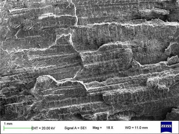

Application of Scanning Electron Microscopy (SEM) in Fracture Analysis of Steel Materials